Contemplating adding a second battery to the Ibex one day, I realised I needed to come up with a suitable split charge system to manage two batteries effectively. Previously I had built and used a great 'smart' battery controller but when it failed (due to high temperatures and operator abuse) it was difficult to quickly overcome the problem and retain a workable twin battery system.
For the Ibex I decided I wanted a simpler solution, which would be easier to operate manually in the event of component failure. The Repair Operation Manual and Parts Catalogues for the Range Rover Classic lists various split charge systems for various model years. The particular one that caught my eye was used on 2-door and 4-door vehicles from mid 1984 to 1985. This features a 'Voltage Sensitive Switch' module which operates a separate 'Split Charge Relay'. The switch simply operates the relay when the supply voltage available rises to approximately 13.0V, and it switches off when the voltage drops below 12.1V.
Instead of using a 'fat' relay to join the batteries together, I have several spare high current solenoids normally used to operate vehicle recovery winches. These are rated for continuous operation (ie can be held 'ON' for long periods) and are capable of conducting high currents without damage (>250A or more for short periods). These devices do suffer occasional damage when used for heavy winching (hence I have spares) but are also used for golf buggies and the like so are pretty reliable if not abused. Having measured the operation current of the solenoid, it draws around 750mA in constant operation so it should be able to be driven directly by the Voltage Sensitive Switch (which has an output transistor rated at around 1A continuous, 2A peak, and diode protection against reverse emf). If there are any problems driving the solenoid, it will be a simple matter to upgrade the output capability.
The solenoids I have are supplied in Warn packaging, but the labelling and part number indicates they are made by Camdec Corporation (apparently now part of Trombetta Motion Technologies). The part number appears on supply lists for GM Military Division, Oshkosh and Mack Trucks, so presumably is of pretty high reliability. There is no supplied specification but a brief survey of the Camdec website suggests the following :-
| Parameter | Specification |
|---|---|
| Coil Voltage | 12V Nominal |
| Duty Cycle | Continuous |
| Break Current | 250A |
| Current Capacity (at max duty) | 125A |
| Contact Inrush Current | 600A |
| Pull In Voltage | 7.0V |
| Hold Voltage | 2.5V |
| Temperature Range | -40C to +60C |
The current specs should allow sufficient capacity to 'jump' a flat battery and start the engine without damage. More importantly the 'pull in' specs indicates that the solenoid will operate when the battery is far too flat to start the engine, and the 'hold' voltage will ensure that the solenoid stays engaged during the current pulses drawn during cranking.
The reason for wanting such a high power relay is twofold. In the first place, the second battery will be used for winch operation and overnight running of a coolbox, and so it is possible it will become completely flattened and draw a very high current from the charging circuit when the engine is first started. In the second place, I will add a manual 'override' switch so that I can 'jump' the main battery if it ever is too discharged to start the vehicle.
I began planning to design a controller for the solenoid, similar in function to the (~£100!!!!!) Range Rover part. However, with plenty of scrap Range Rovers around, it seemed pointless to re-invent the wheel. In addition, having opened a sample device I now know that it would be quick and simple to repair a faulty unit given access to basic electronics equipment. Also I found there is an adjustment available in the unit so it would be easily possible to adjust the set-point if necessary.
Having tested the 'Voltage Sensitive Switch' module, I found that it is working very hard to drive the solenoid coil for long periods. The output transistor runs hot within a few minutes. It is certainly within its' specifications, but I prefer to have a little more 'margin' to enhance reliability. With the benefit of more modern electronic devices, it can be upgraded easily and for only a couple of pounds. I changed the pair of output transistors for a high current MOSFET to reduce the voltage drop and heat generation. I retained the blocking diode, but not for any particular reason. Later as an experiment I replaced the original components to see what the 'real world' reliability would be. After a couple of months use, I have had no failure, so the standard device is probably adequate for most purposes.
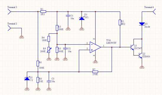
Voltage Sensitive Switch Schematic
I wired the unit into the truck, complete with an on/off switch and warning light, and an override pushbutton to provide 'jumpstart' function. In most vehicles I would not bother with the pushbutton, given that flat batteries are fairly unusual. The main on/off switch allows favouring the main battery (in the case where it is 'flat' and the auxiliary battery is charged) or reducing the average charge to the auxiliary battery (to avoid damage to battery or alternator if the aux. battery is severely discharged).
Notes :
Override Switch FEC 1138766 £8.02
PRC4427 Pinout
| Pin Number | Function |
|---|---|
| 2 | GND |
| 3 | 12V Ignition |
| 4 | Output (Open collector active low) |
Follow up
I've used this setup now for many years without any serious issues. Occasionally there can be some relay chatter if the batteries have very different charge states. This is simply dealt with by overriding the relay on the switch for a few minutes until the voltages begin to equalise.
If I were to redesign I might use a larger hysteresis to prevent chatter completely, and/or I might also consider adding a timeout so the relays don't change state more often than (say) once a minute.
But the system has been effective and mostly fit and forget over the whole period. I have replaced the solenoid listed above with an 80A solenoid from Albright, after I found the contact resistance was getting high (causing slow charge of the auxiliary battery). This may have been caused by repeated switching under load (chatter when winching).