Some notes on Td5 Speedo Reprogramming / Recalibration
The dashboard of 1Bex has for some years used a VDO programmable speedometer, which I fitted for several reasons :-
- No stiff mechanical drive cable to get in the way behind the dash, and in the engine bay
- No LR 'Wibbly Wobbly'™ speedo reading
- Accurate calibration after multiple changes of gearbox, tyre size etc.
A while ago the speedo became unreliable, sometime it reads 0mph all day, sometimes 160mph. The mileometer/tripmeter display became unreliable also, then failed completely. At some point I intended to strip out the speedo and refurbish it, but have never yet got around to it.
Despite these problems, I had intended to obtain a similar unit for use in {tag}2bex . Then a friend donated an used Defender Td5 speedometer. Having never owned a Td5, I wasn't familiar with this design, other than I expected it to be similar to the general purpose VDO design, though not programmable. In practice, it's a nicely made unit, it 'feels' higher quality, and has a much larger display for mileage/trip.
With the help of some knowledge shared by the members of LR4x4.COM here , we can reset the mileage easily so that {tag}2bex can start it's life on 0 miles (well, actually 1 mile, but close enough). I also found in there that efforts had been made ,with partial success, to change the speedo calibration.
I didn't own a suitable EPROM programmer, so I lashed up some simple Micropython code to dump and re-program the EPROM by bit-banging the interface. (Bit-banging is a bit like sending morse code on a light switch, it's slow, ungainly and primitive, but it gets the job done.)
The thread linked also contains all the info needed to make speed calibration possible, only lacking the method to calculate the required checksum value.
Never one to pass over a puzzle lightly, I started assembling useful info in one place, to see what ideas fell out.
Default setting for Defender (reading in MPH) is 4100 pulses per mile.
Land Rover 90/110 speedo drive gears come in four flavours -
Colour: blue/20 teeth - Part number: FRC3310 - Tyres: 7.50/16 or 235/85/16
Colour: green/21 teeth - Part number: FRC3311
Colour: yellow/22 teeth - Part number: FRC3312 - Tyres: 205/16 tyres
Colour: red/24 teeth - Part number: FRC3313
Standard fitment is blue gear on a 110 with 235/85 tyres, giving 4100 pulses/mile.
So if we have 235/85 tyres the calculated diameter is 806mm, giving 636 revs/mile. BFG says 649 revs/mile
285/75 tyres is 834mm, giving 614 revs/mile BFG says 628 revs/mile
4100 = 0x1004 So 0.9676 * 4100 = 3962 = 0x0F7A
So 0x0F7A should be close to the perfect calibration value for the speedo. The work already done in the thread gives a set of 8 checksum values, one of which should work. Case closed? Well, yes, if I could leave the problem well alone...
Curiosity got the better of me, and I decided to see if I could solve the mystery of the checksum calculaton. First step to a solution is always to gather as much data as possible, so start there. Since I already can read and reprogram the EEPROM from a micropython script, then it's a simple step to add control of 12V supply, and generate a fake tacho pulse signal. Then I just needed a way to detect if the speedo was responding to the tacho input or not - detecting needle movement with a light microswitch, or an IR beam break would be trivially simple... (But where's the fun in that?)
OpenMV is a nifty little device that's been looking for a job since it arrived. It's a small development module, carrying a camera module and an STM32 processor running Micropython, and a nifty machine vision library built in. After a couple of hours tinkering, I had built a workable test rig which follows a simple set of steps -
- Select the next calibration value for test
- Select each of 8 checksum values in turn
- Program the eeprom with appropriate values
- Power up the speedo
- Apply a tach signal equivalent to 40mph
- Analyse the camera image to determine if successful
- Record test results
- lather, rinse, repeat...


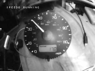
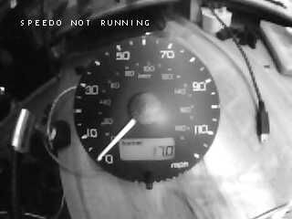
As a check for correct operation, the OpenMV camera saves an image at the end of each test, showing the speedo, marked with the decision taken by the image analysis code. Test cycle time is around 15 seconds.
The image analysis procedure is to isolate the region of interest by finding the speedometer face (look for large round object), then measure the orientation angle of any large straight lines found within the region (the speedo needle). 40mph was chosen as the test speed, as its close to 90 degrees to 0mph. First filter for lines which pass through the centre of the region, then for lines with angles close to 0mph or 40mph equivalent. We keep sampling video frames until we reach confidence in the result (or timeout). This may not be the optimum solution, it was the first I tried and it worked so well, I had no reason to look at alternatives.
After letting the script run for a few hours, I had obtained a set of checksum values for speedo calibration from 25% to 400% of factory setting, in 1% calivbration steps. This should be sufficient reference for any likely use.
A further run established values for every calibration from 2000 to 5556 (got bored of waiting!)

For completeness, I plotted a graph of checksum mask values vs speedo calibration, which made it possible to write an algorithm for the checksum simply by inspection...
Checksum changes every 16 values, so n/16
We know the mask has one of 4 values, so (n/16)%4 generates 0,1,2,3
Looking at the checksum values expressed as binary, its easy to see they are 2x+5 for mask (x) values 0..3
The checksum value is in the high nibble of the check word
The results 'flip' at 4096, so slightly different formula above and below that value.
(The details above are listed only for illustation of the method, the final solution is slightly different)
Following a vague suspicion, further testing showed 'flips' at 8192 and again at 12288.
Finally an inelegant, but complete, solution is arrived at :-
                          tmpval = (RATE >> 4) & 0x0003
                          signbit = RATE & 0x1000
                          offset = RATE >> 12:
                          if signbit:
                                checkword = ((((offset - tmpval) * 2) % 8) + 0x05) << 4
                          else:
                                checkword = ((((offset + tmpval) * 2) % 8) + 0x05)  << 4
Valid calibration values appear to be the range 2000 --> 60000.
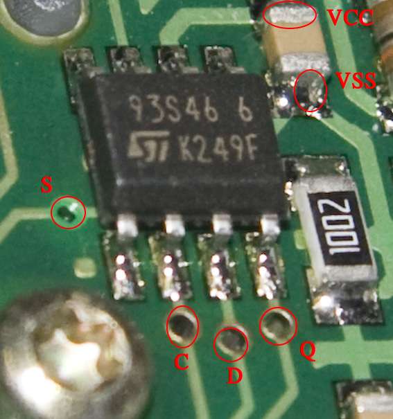
Final task then was to create a python script to run on a raspberry pi, to reprogram the speedo as required. This does require opening the speedo body and soldering on a few wires, but is simple enough for a motivated individual.

| RPi GPIO pin | RPi Signal Name | EEPROM Pin | EEPROM Signal Name |
|---|---|---|---|
| 8 | BCM14 | 8 | VCC |
| 10 | BCM15 | 1 | S |
| 12 | BCM18 | 3 | D |
| 14 | GROUND | 5 | VSS |
| 16 | BCM23 | 4 | Q |
| 18 | BCM24 | 2 | C |
A list of valid check bytes for various calibration values is here.
I haven't published the script for download, but it is available for LR owners on request. I'm not concerned with mileage correction, since the details for doing that are already in the public domain, and commercial services are available to achieve that for those that want it for their own reasons.